Motors and Open Loop Control
The purpose of this lab was to change from manual to open loop control of the RC car using the Artemis Nano board and the dual motor brushed DC motor drivers
Prelab
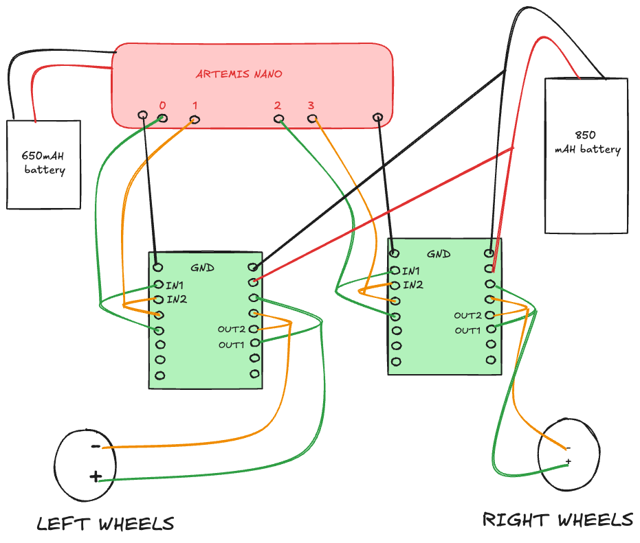
I began by figuring out how I wanted to wire the motors given that they had to be parallel coupled. Additionally, I wanted to also consider routing paths, given EMI, wiring lengths and color coding that will fit the RC car and be functional. I used the following pins to wire up the motors:
- GND Pins: One Wired to GND pin on the Artemis and the other to the negative terminal of the battery
- VIN: Wired to the positive terminal of the battery
- AIN1 & BIN1: Paired and wired to Artemis pins
A0on left motor andA2on right motor - AIN2 & BIN2: Paired and wired to Artemis pins
A1on left motor andA3on right motor - AOUT1 & BOUT1: Paired and wired to the positive motor lead for each motor
- AOUT2 & BOUT2: Paired and wired to the negative motor lead for each motor
I coupled the input and output pins of the motors to increase the effective current being drawn. This means we can get more current to the motors. I also made sure the pins used are analong PINS so that I can send PWM signals to the pins.
The schematic below shows a rough outline of the wiring.
 Wiring
Although the Artemis is powered by a 650 mAh battery, I powered the motors with an 850 mAh battery. They are separated to avoid noise or voltage drops from the motors affecting the board’s operation. Additionally, an 850mAh battery supports the motor drivers’ higher energy needs.
Lab Tasks
To begin my wiring, I started by soldering the necssary power and signal inputs of one motor driver according to the wiring I designed in the Prelab section.
To test the connection, I hooked up the motor driver to a VIN from an external power supply set at 3.7V. I chose this value because it is slightly above the 3.3V out of the Artemis so
I know that the motor driver will be getting enough power to run the motors. According to the datasheet, a forward spin of the wheels corresponds to keeping one pin HIGH and the other LOW.
I then used analogWrite() to send a PWM signal to the motor driver.
Below is the code I used to test the motor driver. Here I am sending a PWM signal to the left motor driver to spin the wheels forward.
void setup() {
  pinMode(0, OUTPUT);
  pinMode(1, OUTPUT);
}

void loop(){
    for (int i = 0; i < 255; i++) {
        analogWrite(0,255-i)
        analogWrite(1,0);
        delay(10);
    }
}
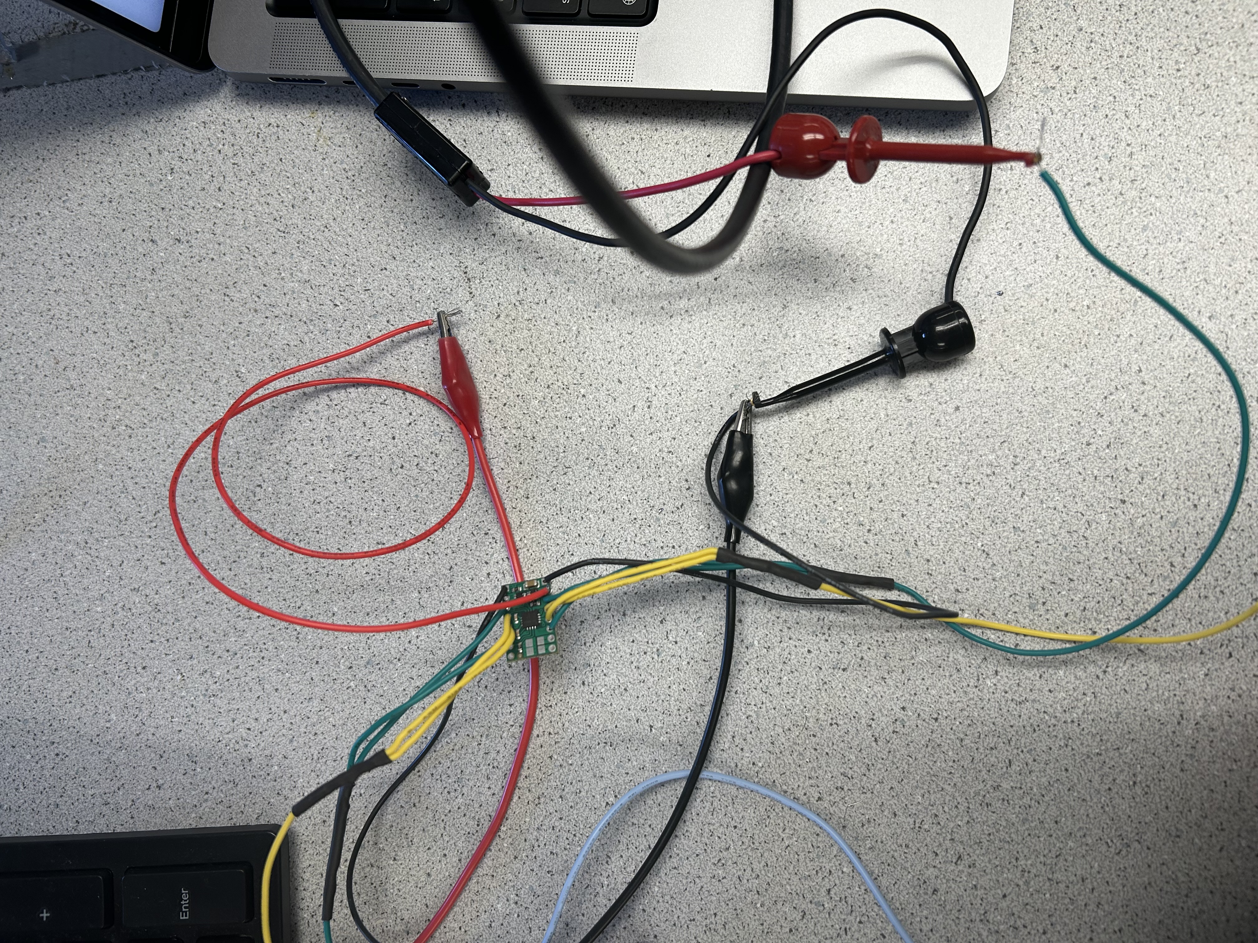 Motor Driver
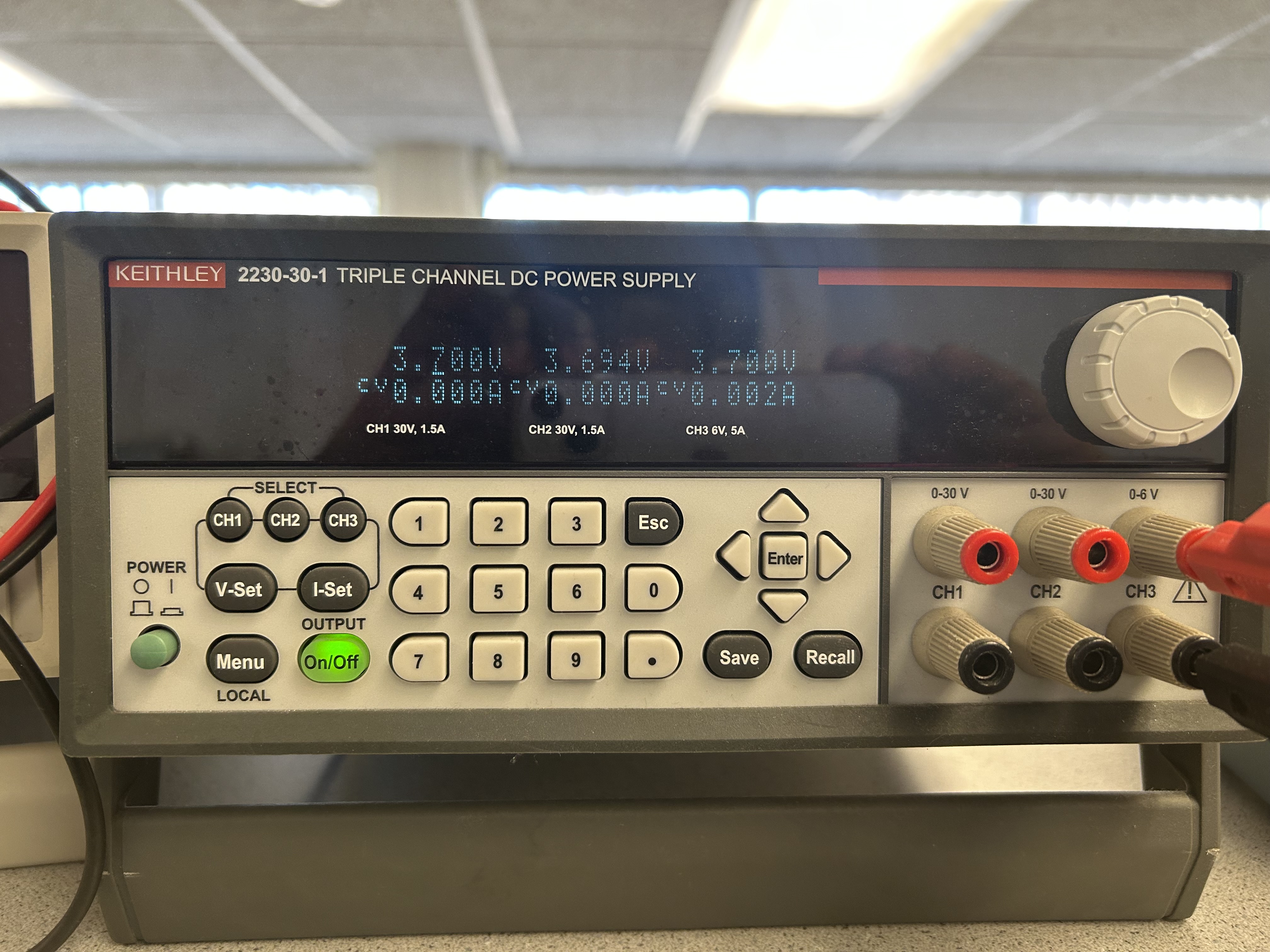 3.7V Power Supply
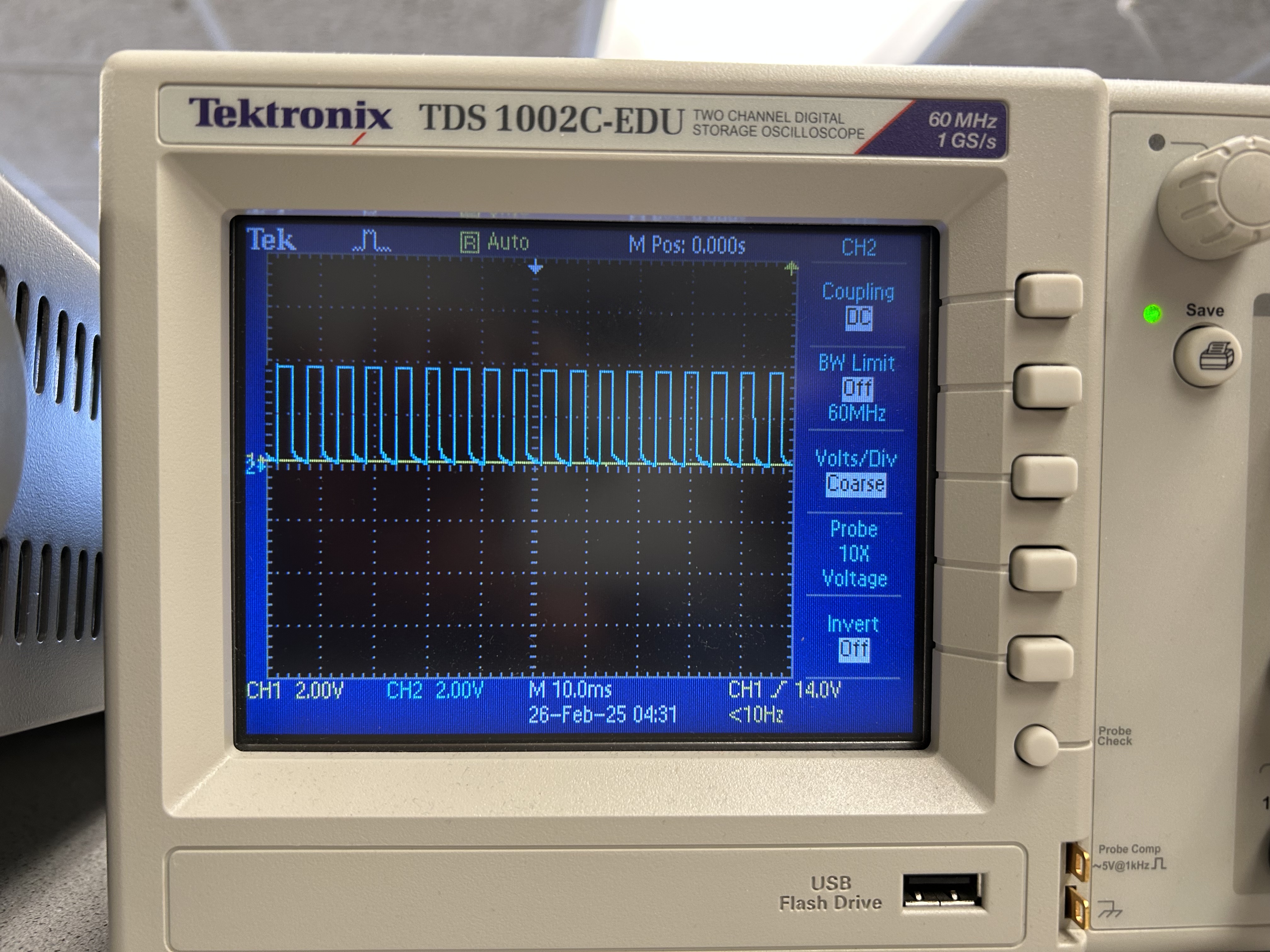 Oscilloscope
And here is a short video of the wheels spinning. I am using a forward PWM signal
Following this, I soldered the second motor driver, took the car apart completely, and wired it up to the Artemis.
Final Car Assembly
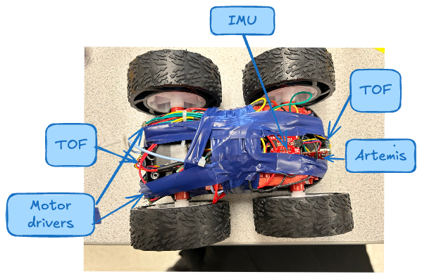 Complete schematic
From here, the permanent soldering of the motor drivers is complete and I wrired it with the 850mAh battery. The following video shows both wheels spinning.
And here is a video in slow motion of the wheels spinning in both directions. This shows my motor can spin in reverse and forward PWM. The code to achieve this is:
analogWrite(0, 0);
analogWrite(1, 200);

analogWrite(2, 200);
analogWrite(3, 0);
Lower Limit of PWM
To determine the lower limit of PWM, I increased it in increments of 5 to find the signal at which the motors that to spin. From my experiment, I concluded that the car needs about PWM of 35-40 to move forward on-axis while on the ground.
Calibration
I investigated if my motors were spinning at the same rate by giving both motors the same PWM and seeing how it moved in a straight line.
I created a function called drive_in_a_straight_line(int direction, int pwm, float calib). This function was helpful as I could easily configure my motors
to spin forward or backward at some rate given some calibration factor. I also created a stop function so I could drive in a straight line for a bit, and then stop.
void drive_in_a_straight_line(int direction, int pwm, float calib) {
  if (direction) {  // forward
    analogWrite(0, pwm);
    analogWrite(1, 0);
    analogWrite(2, pwm * calib);
    analogWrite(3, 0);
  } else {
    // reverse
    analogWrite(0, 0);
    analogWrite(1, pwm);
    analogWrite(2, 0);
    analogWrite(3, pwm * calib);
  }
}

void stop() {
  analogWrite(0, 0);
  analogWrite(1, 0);
  analogWrite(2, 0);
  analogWrite(3, 0);
}
The video below shows what that looked like before calibration. Since the car skews to the right, it means the left motor is spinning faster than the right motor.
Hence I multiplied the right PWM by a calibration factor of 1.25 to make the right motor spin at the same rate.
The results of this calibration are shown below. They car now moves in a fairly straight line!
Open Loop
To demonstrate open loop control, I integrated turns into the code and after some experiment I tuned the right delay needed to make a right or left turn.
By playing with each pair of wheels pinning in reverse and forward pwm, I cause the motor to spin left/right. I used some handy methods in addition to my
drive_in_a_straight_line() function to make the turns.
void turn_right(int pwm) {
// Left wheels spin forward
 analogWrite(0, pwm);
analogWrite(1, 0);

// Right wheels spin backward
analogWrite(2, 0);
analogWrite(3, pwm);
}

void turn_left(int pwm) {
// Left wheels spin backward
analogWrite(0, 0);
analogWrite(1, pwm);

// Right wheels spin forward
analogWrite(2, pwm);
analogWrite(3, 0);
}
Then I can use theese functions to drive the car in different ways
void loop(){
  drive_in_a_straight_line(1, 150, 1.25);
  delay(1000);
  stop();
  delay(2500);
  turn_right(150);
  delay(1000);
  stop();
  drive_in_a_straight_line(1, 150, 1.25);
  delay(2500);
  turn_left(150);
  delay(1000);
  stop();
}
Here is a demo of the car driving this path. The car begins by driving straight, turns right (which is a right spin because of the delay while turning right), it drives straight again, and consequently spins left. (Don't mind the stool in the way :))
Discussion
This was an overall fun but challenging lab. It was challenging to get the motors all soldered together correctly. It was also difficult to debug issues with the hardware especially when testing outside of lab. Ultimately, I learned a lot about the RC car and how to control it using the motor drivers and open loop control. I am curious to see how PID control of the car would improve its performance.
References
[1]Nila Narayan