Orientation Control
The purpose of this lab was to implement a PID controller for orientation control of the RC car. The goal was to make the car turn to a setpoint angle and maintain that angle.
Prelab
This lab was a continuation of the previous lab on PID control with the Tof Sensors. In this lab, we were to use the gyroscope on the IMU to gather data on the car's orientation and use that data to control the car's orientation towards a target angle. Fortunalely, most of the infrastructure for this lab was already in place. I simply re-used the same code from the previous lab but swapped out the sensor readings for the gyroscope readings.
Lab Tasks
To begin, collecting the gyroscope data was not exactly trivial. As we had seen in Lab 2, the gyroscope is susceptible to drift, which can become problematic when implementing closed-loop control. To mitigate this, I configured the onboard Digital Motion Processor (DMP) which is capable of error and drift correction by fusing readings from the ICM's 3-axis gyroscope, accelerometer and magnetometer. A key point to note here is that setting the DMP mode to 1INV_ICM20948_SENSOR_GAME_ROTATION_VECTOR` will configure the IMU to poll at 1.1KHz maximum rotational velocity for the gyroscope to 2000 degrees per second (dps) which has been proved to be enough. Many thanks to Stephan Wagner (2024) for this insight. This isn't configured by default, so I took the following steps to configure it:
- I uncommented line 29
ICM_20948_USE_DMPin theICM_20948_C.hheader file to enable the DMP - Then in the setup function, I added the following code to configure the DMP:
  bool success = true;
  success &= (myICM.initializeDMP() == ICM_20948_Stat_Ok);

  // Enable the DMP orientation sensor and set to 2000 dps
  success &= (myICM.enableDMPSensor(INV_ICM20948_SENSOR_GAME_ROTATION_VECTOR) == ICM_20948_Stat_Ok);

  // Configure DMP to output data at maximum ORD
  success &= (myICM.setDMPODRrate(DMP_ODR_Reg_Quat6, 0) == ICM_20948_Stat_Ok);

  // Enable the FIFO
  success &= (myICM.enableFIFO() == ICM_20948_Stat_Ok);

  // Enable the DMP
  success &= (myICM.enableDMP() == ICM_20948_Stat_Ok);

  // Reset DMP
  success &= (myICM.resetDMP() == ICM_20948_Stat_Ok);

  // Reset FIFO
  success &= (myICM.resetFIFO() == ICM_20948_Stat_Ok);

  // Check success
  if (!success) {
    Serial.println("Enabling DMP failed!");
    while (1) {
      // Freeze
    }
  }
  Serial.println("DMP configuration successful!");
PS: I learned the hard way that this configuration must come after the initialization of the ICM. Otherwise, the DMP will not work.
Once this was set up, I created a new function called record_dmp_data(), which will continously read the DMP FIFO for quarternions, which are then
converted to Euler angles. I also made sure to add a slight delay between readings if there was no more data in the FIFO. This ended up looking like the following:
void record_dmp_data() {
  icm_20948_DMP_data_t dmp;
  myICM.readDMPdataFromFIFO(&dmp);

  // Check if the myICM has data
  if ((myICM.status != ICM_20948_Stat_Ok) && (myICM.status != ICM_20948_Stat_FIFOMoreDataAvail))
    return;

  // Check for Quat6 orientation data
  if ((dmp.header & DMP_header_bitmap_Quat6) <= 0) {
    Serial.println("No quaternion data available");
    return;
  }

  // Scale to +/- 1
  qx = ((double)dmp.Quat6.Data.Q1) / 1073741824.0;
  qy = ((double)dmp.Quat6.Data.Q2) / 1073741824.0;
  qz = ((double)dmp.Quat6.Data.Q3) / 1073741824.0;

  qw = sqrt(1.0 - min(((qx * qx) + (qy * qy) + (qz * qz)), 1.0));

  siny = 2.0 * (qw * qz + qx * qy);
  cosy = 1.0 - 2.0 * (qy * qy + qz * qz);
  yaw_gy = (float)(atan2(siny, cosy) * 180.0 / PI);

  // Only delay between readings if no more data is available
  if (myICM.status != ICM_20948_Stat_FIFOMoreDataAvail) {
    delay(10);
  }
}
Once this set up was out of the way, I added a few more things to make this work in general. First, I added a new command SET_SETPOINT which
allows me to set the setpoint angle via bluetooth so I didn't have manually change and recompile the code every time I wanted to test a new setppint.
I also adjust the drive_in_a_straight_line() function from the previous to generate a differential drive instead. This means the left and right wheels will spin
in opposite directions to cause a turn.
void drive_in_a_straight_line(int direction, int pwm, float calib) {
  if (direction) {
    analogWrite(0, pwm * calib);
    analogWrite(1, 0);
    analogWrite(2, pwm * calib);
    analogWrite(3, 0);

  } else {
    analogWrite(0, 0);
    analogWrite(1, pwm * calib);
    analogWrite(2, 0);
    analogWrite(3, pwm * calib);
  }
}
Tuning the PID
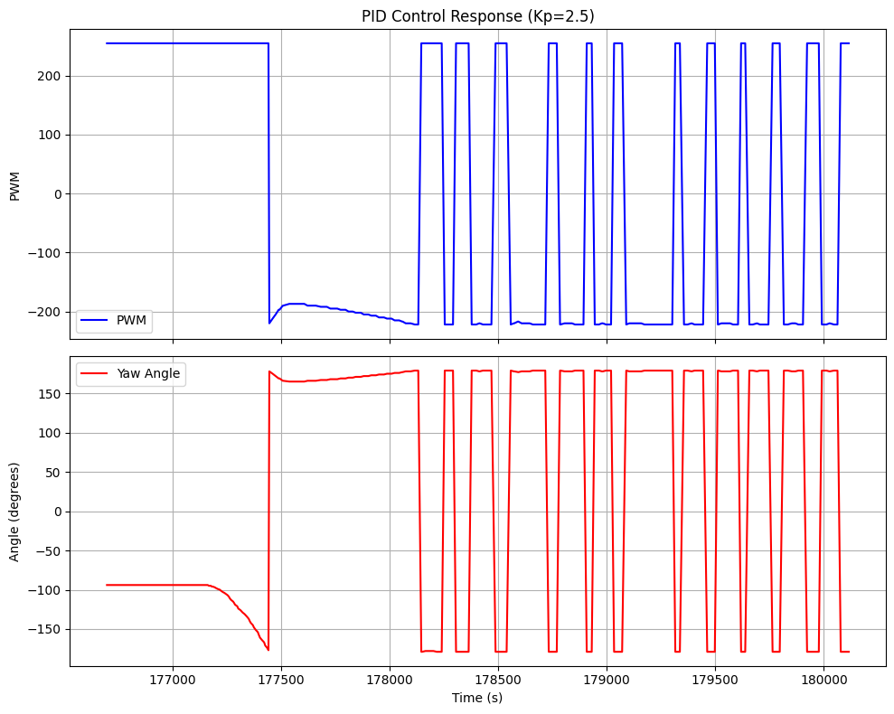
I began tuning the PID by using only a proportional controller. I started with a kp of 2.5. This seemed like a good starting point based on what have been done in the previous years. The car was able to start at an angle different from the setpoint and will eventually turn and converge to the setpoint as seen in the video below.
Below is a plot of this response. It is quite clear (including from the video) that the car intiially overshoots and then oscillates back and forth. At this point, I knew I need to add a differential controller to reduce the oscillations. However, in the process I ended up adding an integral controller as well.
 Oscillations
My PID contoller method is now becomes:
int pid_control(int curr_angle) {
  int error = pid_target - curr_angle;

  unsigned long current_time = millis();
  float dt = (float)(current_time - last_pid_time) / 1000.0;  // Convert ms to
  last_pid_time = current_time;

  if (dt > 0) {
    accumulated_error += error * dt;
  }

  // Calculate P and I terms
  float p_term = kp * error;
  float error_rate = 0.0;
  if (dt > 0) {
    error_rate = (error - prev_error) / dt;
  }
  float d_term = kd * error_rate;
  float i_term = ki * accumulated_error;
  if (i_term > 200) {
    i_term = 200;
  } else if (i_term < -200) {
    i_term = -200;
  }

  float pwm = p_term + d_term + i_term;
  prev_error = error;

  if (pwm > 0 && pwm > 255) {
    pwm = 255;
  } else if (pwm < -255) {
    pwm = -255;
  }

  return pwm;
}
Over many iterations, I finally tuned my PID to a kp = 2.5, ki=0.02 and a kd=0.7. The below video shows my car turning to the setpoint without any initial overshoot. Although it still oscillates, it is much more stable now. Finally, I was able to disturb the car and it would turn back to the setpoint again.
Conclusion
Overall, this lab was quite similar to the previous one. It was very clutch to have most of the infrastructure already setup. However, I had to adjust some things such as taping the wheels to reduce friction because the car needed relatively high pwm to turn on its axis. It was also great to implement DMP to reduce drift in the gyroscope.